Introduction
Surface-mount technology (SMT) has revolutionized electronics by allowing components like capacitors to be placed directly onto printed circuit boards (PCBs) with high precision. Among these, the 20V 1000uF SMD 4 x 5.4mm Electrolytic Capacitor KiCad is widely used in various circuits, from power supply filtering to energy storage.
For beginners in electronics and PCB design, KiCad offers a free and powerful platform to design schematics and layouts. Understanding how to integrate this specific capacitor in KiCad can save time, reduce errors, and enhance circuit reliability. This guide walks through the process in a friendly, step-by-step manner, making it perfect for novices and hobbyists.
Understanding the 20V 1000uF SMD Electrolytic Capacitor
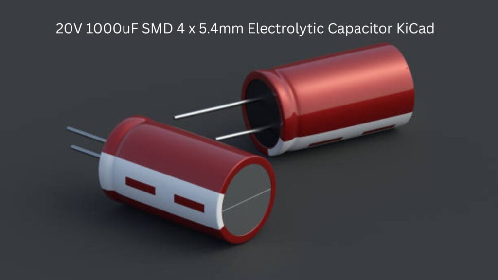
Before diving into KiCad, it’s essential to understand the component itself. The 20V 1000uF SMD 4 x 5.4mm Electrolytic Capacitor KiCad has three primary specifications:
- Voltage Rating (20V): This indicates the maximum voltage the capacitor can safely handle without breaking down. Using a voltage above this can damage the component.
- Capacitance (1000uF): Capacitance determines how much charge the capacitor can store. In circuits, 1000uF is ideal for smoothing power supply ripples or storing temporary energy.
- Physical Size (4 x 5.4mm): The compact dimensions make it suitable for surface-mount applications where space is limited. Designers must choose the correct footprint in KiCad to match this size.
Electrolytic capacitors are polarized, meaning they have a positive and negative terminal. Proper orientation is crucial during PCB design to prevent circuit failure. Unlike SMD ceramic capacitors, electrolytic capacitors are better for high-capacitance applications.
Getting Started with KiCad
KiCad is an open-source PCB design tool that allows users to create schematics, design PCB layouts, and even generate manufacturing files. Beginners often find it approachable due to its intuitive interface and extensive library support.
Installing KiCad
- Visit the official KiCad website and download the latest version compatible with your operating system.
- Follow the installation instructions. The software includes both schematic and PCB layout tools.
Creating a New Project
- Open KiCad and click “File → New Project”.
- Name your project and select a folder location. This becomes the workspace for your schematic and PCB files.
Understanding the workflow in KiCad is essential: you first create a schematic with all components, then assign footprints, and finally design the PCB layout.
Adding the Capacitor to Your Schematic
Adding the 20V 1000uF SMD 4 x 5.4mm Electrolytic Capacitor KiCad to your schematic is straightforward, but beginners must follow specific steps to avoid mistakes.
Finding the Capacitor Symbol
- Open the Schematic Editor in KiCad.
- Click “Place → Component”, and search for “electrolytic capacitor.”
- Select a symbol that supports polarized electrolytic capacitors. Ensure it can handle 20V and 1000uF for reference.
Connecting the Capacitor
- Place the component on your schematic.
- Connect it to other components using wires. For instance, in a power supply circuit, one terminal connects to the positive rail, while the other goes to the ground.
Tips for Proper Placement
- Always ensure the polarity is marked clearly in your schematic.
- Avoid overlapping wires to keep the schematic readable.
- Group capacitors logically near power input or voltage regulator sections.
Designing the PCB Footprint for 4 x 5.4mm SMD Capacitor
Once the schematic is complete, the next step is the PCB layout. The footprint ensures the physical component fits the PCB accurately.
Understanding Footprints
- A footprint defines the pad layout, spacing, and mechanical dimensions for the component.
- For a 4 x 5.4mm SMD capacitor, the footprint must reflect the size accurately to avoid soldering issues.
Selecting or Creating the Footprint
- KiCad has built-in libraries with standard capacitor footprints. Search for SMD 4×5.4mm electrolytic.
- If unavailable, create a custom footprint:
- Open Footprint Editor → New Footprint.
- Set pad dimensions and spacing to match the capacitor datasheet.
- Include polarity markings.
Placement Tips
- Position the capacitor close to the voltage regulator or power supply source to minimize ripple.
- Keep traces short and wide to handle high currents.
- Avoid placing the capacitor near heat sources that may affect lifespan.
Routing and Finalizing Your PCB
Proper routing ensures the capacitor performs optimally in your design.
Placement for Power and Ground
- Connect the positive pad to the supply rail.
- Connect the negative pad directly to the ground plane.
Using Vias and Traces
- Use thick traces for high-current paths.
- Minimize vias to reduce inductance and resistance.
Common Pitfalls to Avoid
- Swapping polarity leads, which can cause capacitor failure.
- Placing the capacitor too far from the load, increasing voltage ripple.
- Ignoring clearance rules; ensure pads and traces don’t short with other components.
Simulation and Testing in KiCad
KiCad allows basic simulation through ngspice integration, which can be useful to check capacitor behavior in the circuit.
How to Simulate Capacitor Behavior
- Add a transient analysis in your schematic to observe voltage smoothing effects.
- Verify that the capacitor discharges and charges as expected under typical load conditions.
Verifying Design Rules
- Run the DRC (Design Rule Check) to ensure proper spacing and connections.
- Check that the 4 x 5.4mm footprint matches the component physically to prevent soldering errors.
Simulation is optional for beginners but highly recommended for critical power designs.
Conclusion
Integrating a 20V 1000uF SMD 4 x 5.4mm Electrolytic Capacitor KiCad may seem challenging at first, but breaking the process into clear steps makes it manageable. Understanding the capacitor specifications, adding it correctly to the schematic, designing the footprint, and carefully routing it in the PCB ensures your design is reliable and efficient.
Beginners are encouraged to experiment with placement, trace width, and capacitor values while following best practices for polarity and grounding. With consistent practice, using SMD electrolytic capacitors in KiCad will become second nature.
FAQs
Q1: What is the lifespan of a 20V 1000uF SMD electrolytic capacitor?
Typically, these capacitors last 2,000–5,000 hours at rated voltage and temperature. Lifespan decreases with higher temperature and voltage stress.
Q2: Can I use a different size capacitor in KiCad?
Yes, but you must match the footprint and electrical specifications. Mismatched sizes may cause mechanical and electrical issues.
Q3: How to choose between SMD and through-hole capacitors?
SMD capacitors are ideal for compact, automated PCB production, while through-hole capacitors are better for high-stress or high-current applications.